Updated 2021-04-21
Introduction
There have been contradictions regarding the application of the voltage drop test limit specified in CSA Z32 and how it is used in determining whether a branch circuit meets the criteria of Rule 8-102 in CSA C22.1.
The intent of the voltage drop test is to determine whether a branch circuit in a health care facility can adequately supply power to connected equipment via the receptacle. It is a measure of performance with limits set by the Canadian Electrical Code.
Subrule (1) Items (a) and (b) of Rule 8-102 in CSA C22.1 states:
1) The voltage drop in an installation shall be based on the connected load of the feeder or branch circuit if known; otherwise it shall be based on 80% of the rating of the overload or overcurrent device protecting the branch circuit or feeder, and not exceed
a) 3% in a feeder or branch circuit; and
b) 5% from the supply side of the consumer’s service (or equivalent) to the point of utilization.
The limits 3% and 5% are interpreted as 3% of the voltage at the point-of-supply and 5% of the voltage at the point-of-supply respectively.
Clause 5.4.3.2 of CSA Z32 states:
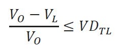
The voltage drop (VO – VL ) shall not exceed 5% of VO
The test limit of 5% specified in Clause 5.4.3.2 does not meet the requirements of Rule 8-102 in the Canadian Electrical Code.
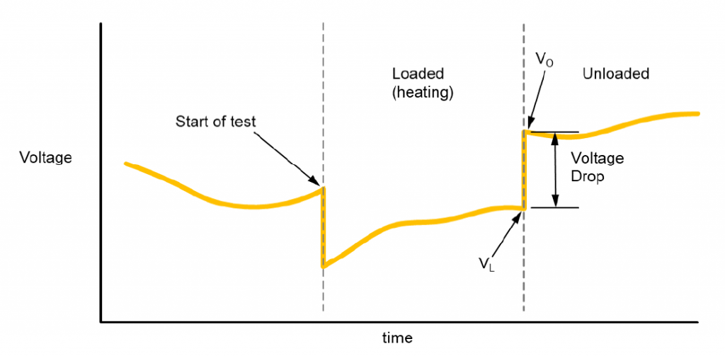
The problem is that the voltage drop test does not actually measure the branch circuit voltage drop. The test results are used instead to infer the performance level of the branch circuit. The test makes two measurements at one point under different loading conditions: loaded to 80% of capacity, and then unloaded.
This analysis will show that the test results can be used to ascertain the performance level of the branch circuit. The theoretical analysis that follows will show the derivation of a test limit that meets the requirements of Rule 8-102 in the Canadian Electrical Code.
Terminology
To aid the reader, the following terminology will be used:
| VS | the voltage at the point-of-supply as supplied by the electrical distributor at the transformer secondary |
| VF | the feeder voltage at the panelboard |
| VU | the voltage at the point-of-utilization (receptacle) |
| VL | the voltage at the point-of-utilization under load during the voltage drop test |
| VO | the voltage at the point-of-utilization (un-loaded) during the voltage drop test |
| IF | the current equal to the rating of the overload or overcurrent device protecting the feeder circuit |
| IB | the current equal to the rating of the overload or overcurrent device protecting the branch circuit |
| RF | the lumped real part of the impedance of the feeder circuit including contactors/breakers and wire |
| RR | the lumped real part of the impedance of the remaining branch circuits including breakers, joints/splices, contact points and wire |
| RB | the lumped real part of the impedance of the branch circuit including breakers, joints/splices, contact points and wire |
| RL | the load at the point-of-utilization used during the voltage drop test |
| SW | the switch used to connect and disconnect the load (RL) during the voltage drop test |
| VDSUS | the normalized voltage drop from VS to VU with respect to VS |
| VDSFS | the normalized voltage drop from VS to VF with respect to VS |
| VDFUS | the normalized voltage drop from VF to VU with respect to VS |
Feeder and Branch Circuits
Simplified diagrams of a feeder circuit and corresponding branch circuits are shown below for reference:


Rule 8-102
The voltage drop (from point-of-supply to point-of-utilization) in the building electrical system is comprised of the sum of the voltage drop in the feeder circuit and the voltage drop in the branch circuit.

Using Rule 8-102 along with the preceding definitions, the upper limit of the voltage drop in the branch circuit can be defined as:

and the total limit can be rewritten as,

which can be reduced to,

Analysis
A distinction is made between absolute voltages either at the receptacle or the supply, and the performance of the building electrical system within the health care facility.
Absolute Voltages
Care should be taken to avoid requirements of an absolute voltage level at the point-of-utilization when assessing the performance of the building electrical system in a health care facility. Although in a practical sense, an adequate voltage level at the receptacle is necessary for connected equipment to work properly, the voltage level is largely a function of the voltage at the point-of-supply. If the building electrical system performs adequately, and the electrical distributor supplies the facility with an adequate voltage level, it follows that the voltage available at the point-of-utilization (receptacle) will be adequate. The building electrical system is merely a “conduit” that transfers the supplied voltage through the facility to the receptacle.
The electrical distributor supplies the facility (when not using local back-up generation) to the feeder circuit via transformer. The supply voltage is provided by the electrical distributor and outlined in a document termed “Conditions of Service”. This document (as required per the “Distribution System Code” (DSC) in Ontario for example) communicates the type and level of service available to customers and consumers.
Within the “Conditions of Service” are “Voltage Guidelines” specifying what voltages customers and consumers can reasonably expect (with reference to CAN3-C235). Both “Normal Operating Conditions” and “Extreme Operating Conditions” ranges are provided from CAN3-C235. Electrical distributors do not guarantee operation within the “Normal Operating Conditions” range – they strive, or endeavor to maintain the voltage within that range. If the supply voltage falls outside the “Normal Operating Conditions” range, and within the “Extreme Operating Conditions” range, they are not obligated to implement improvement or corrective action. If the supply voltage falls outside the indicated limits of the “Extreme Operating Conditions” range, the electrical distributor may take improvement or corrective action on an emergency basis depending on a number of factors.
The level of performance of the building electrical system in a health care facility cannot be determined based on the absolute measured voltage at the point-of-utilization, (VU) as it is largely a function of the voltage at the point-of-supply (VS).
Performance of the Building Electrical System
The analysis of the performance of the building electrical system will be limited to the branch circuit. This
is the portion of the electrical system from the panelboard (including the branch circuit breaker) up to the
point-of-utilization (including the receptacle).
The diagram of the feeder circuit and branch circuits is re-drawn below to aid in derivation of the voltage
drop test limit for verification of the branch circuit.
Figure 3 and Figure 4 show the feeder circuit with lumped impedance RF, the branch circuit under test with
lumped impedance RB, the switch SW, and the load RL. The lumped impedance of the remaining branch
circuits are shown as RR.
The voltage at the point-of-supply is indicated by VS, the feeder voltage (at the panelboard) by VF, and the
voltage at the point-of-utilization by VU.
The circuit in Figure 3 represents the state of the system during the first part of the voltage drop test where
the conductors and associated connections of the branch circuit under test are subjected to a current
equaling 80% of the rating of the overcurrent device protecting the branch circuit. The circuit in Figure 4
depicts the last step of the test where a reading of VF is made when the switch (SW) is opened.


Voltage Drop Test – Overview
The voltage drop test involves the measurement of the voltage available at the receptacle under 80% loaded and unloaded conditions. It is imperative that the measurements are made in quick succession (and perhaps multiple times) to reduce the probability of an erroneous result due to supply voltage variations. A heating interval is required before the measurements are made (while loaded) to reveal potential connection issues however the five second period specified in CSA Z32 may be too short. According to an analysis of electrical receptacle fires (Matthew E. Benfer and Daniel T. Gottuk, 2013), the approximate peak-to-peak time for voltage drop oscillation based on temperature rise for compromised connections varied and was as high as three minutes. This suggests that the five second heating interval described in CSA Z32 may not be long enough to reveal a compromised connection.
Voltage Drop Test – Loaded
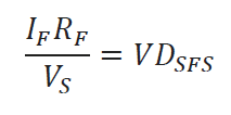
With switch SW closed, the voltage drop across RF is VDSFS, and the voltage drop across RB is VDFUS.
In this state, and using Figure 3 as a reference, it follows that:

and,

then,
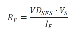
Solving for RF,
Also,
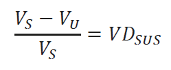
and since, during the loaded phase of the test,

then,

Voltage Drop Test – Unloaded
When switch SW is opened, the feeder voltage, VF is measured at the point-of-utilization, VU. This is also known as the terminal voltage without load (VO) as described in Clause 5.4.3.1 of CSA Z32.
The current through RF is reduced by an amount equal to the current flowing through RB (during the loaded portion of the voltage drop test):

As VO is equal to VF (measured at the point-of-utilization when switch SW is opened),

Substituting the value for RF into the above equation yields:


Test Limit
It is important to note that the following voltage drop test limit is the maximum acceptable value to used infer the performance of the branch circuit only and is not a voltage drop as a percentage of the voltage at the point-of-supply. However, meeting the test limit confirms that the branch circuit meets the criteria of Subrule (1) Item (a) of Rule 8-102 in CSA C22.1, Part I.
The voltage drop test limit referenced in Clause 5.4.3.2 is:


After substitution of equation (4), a limit can now be established based on the ratings of the overload or overcurrent devices protecting the feeder and branch circuits, and the voltage drop in the feeder circuit.

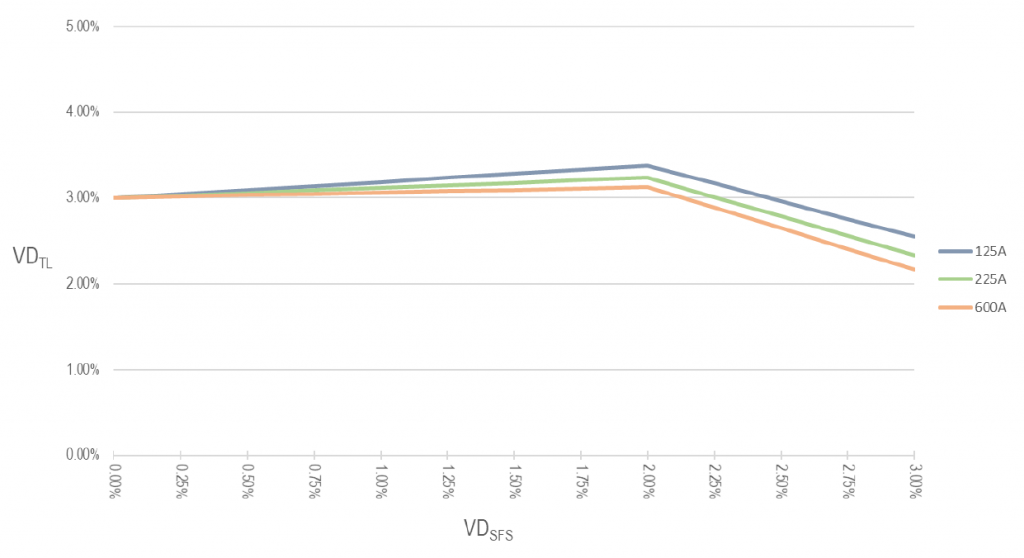
Equation (19) is more complex than the 5% value listed in Clause 5.4.3.2 and difficult to use in practice when performing testing. Using equation (19), a plot of three panelboard sizes of 125 A, 225 A, and 600 A for a 15 A branch circuit is shown in Figure 6 and a 20 A branch circuit in Figure 7. The greatest test limit is 3.3% for a 15 A branch circuit and 3.38% for a 20 A branch circuit fed from a 125 A panelboard. These peaks occur when the feeder circuit voltage drop is at 2% of the voltage at the point-of-supply.
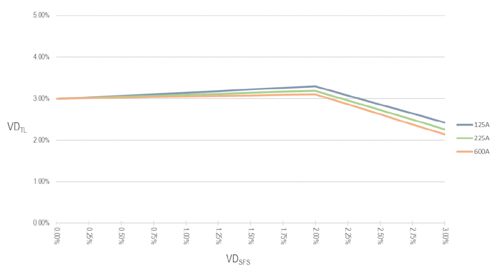
Although calculations can be performed for each branch circuit, the voltage drop in the feeder circuit is still unknown. As Figure 6 and Figure 7 shows, the voltage drop test limit is close to 3% up to a 2% voltage drop in the feeder circuit.
Conclusion
It can be reasoned for practical purposes that a limit of 3% should be used as the voltage drop test limit. If it is found that the feeder circuit voltage drop exceeds 2%, calculations can be performed to investigate whether Rule 8-102 has been compromised and corrective action can be taken if necessary using equation (19) and other means.
An argument can be made that in most cases it would be less costly to correct a deficient feeder circuit than several branch circuits.
It is recommended that the following voltage drop test limit be used with the provision that the voltage drop in the feeder circuit not exceed 2% of the voltage at the point-of-supply:

References
- Canadian Standards Association. (2015, December). Electrical safety and essential electrical systems in health care facilities (CSA Z32-15). Toronto, Ontario, Canada: CSA Group.
- Canadian Standards Association. (2018, January). Canadian Electrical Code, Part I (CSA C22.1). Safety Standard for Electrical Installations. Toronto, Ontario, Canada: CSA Group.
- Canadian Standards Association. (2019, December). Preferred voltage levels for AC systems up to 50 000 V (CSA C235:19). Toronto, Ontario, Canada: CSA Group.
- Matthew E. Benfer and Daniel T. Gottuk. (2013). Development and Analysis of Electrical Receptacle Fires. Baltimore: U.S. Department of Justice.
