The ground return path voltage rise test is performed to measure the grounding effectiveness of the bonding conductor and other associated ground path conductors in all health care facilities (including hospitals and clinics). The explanation that follows is provided as a general guide and should only be performed by qualified personnel using the appropriate test equipment. Please consult the current applicable electrical safety codes in effect for your area. The complete test procedure is outlined in clause 5.10 “Ground return path voltage rise for solidly grounded systems” within the CSA Z32 standard and should be consulted.
The test requires injection of a controlled, simulated fault current (from the receptacle under test) returning to the source ground through the ground path for anywhere between one and five seconds. This simulated fault current is adjusted to 80% of the rated current of the circuit and is flowing throughout the duration of the test.
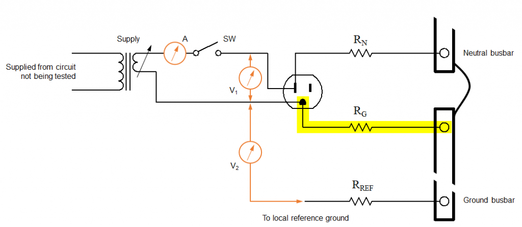
The components RN, RG, and RREF in the diagram above represent the lumped conductor/connection resistances for the neutral, receptacle ground, and reference paths respectively – they are not discrete resistors.
As no conductor or connection is perfect, there will be a measurable rise in voltage at meter “V2” when the simulated fault current is injected (SW closed) compared to a “no current” condition (SW opened).
Test Procedure
- With the switch (SW) open, measure the voltage using meter “V1” and record the value as VN. This is the neutral to ground voltage and is ideally 0 V.
- The supply (shown in the diagram) is used as an AC current source for injection of the simulated fault current. Close the switch (SW) and ensure that the current read by meter “A” is 80% of the rated current of the circuit for the duration of the test. This is essentially a short-circuit as neutral and ground are connected within the panelboard. For accuracy, the supply should be powered from a separate circuit. Record the current using meter “A” as IN, and the voltage using meter “V2” as VR (the ground return path voltage rise).
Test Results
When the entire test is complete, you will end up with three measurements:
- The simulated fault current, IN
- The neutral to ground voltage, VN
- The ground return path voltage rise, VR
The ground return path voltage rise (VR) shall not exceed 3 V.
Example
Suppose you perform the test on a CSA 5‑15R receptacle configuration (120 V nominal and 15 A rated current) and record the following measurements:
IN = 12 A (this is 80% of the rated current, or 0.8 × 15 A = 12 A)
VN = 0.75 V
VR = 1.23 V
This is an example of a circuit that has passed the test as the ground return path voltage rise is less than the 3 V maximum specified by Clause 5.10.2.1.2 of CSA Z32.
What to watch out for…
- The current path in this test is essentially a short circuit. Care should be taken to avoid interruptions at the receptacle (connecting or disconnecting the test plug when the supply is energized) as it may result in pitting of the contacts inside the receptacle.
- Even if the ground return path voltage rise (VR) is less than 3 V, you must ensure that 80% of the rated current of the circuit was flowing in the circuit before you can state that the test has passed.
How often should this test be performed?
This test is performed upon completion of new construction or major renovation, when additions are made to existing installations, or when a receptacle is replaced.
What test equipment do I need?
The ALTS2400 CSA Z32 Test System will perform ground return path voltage rise tests quickly and easily for grounded 120 V circuits (15 A and 20 A).