The hazard index in an isolated power system is expressed as a current in milliamperes (mA) consisting of leakage and fault currents that would flow between an isolated conductor and ground through a low impedance path (refer to the CSA Z32 standard for the complete definition).
The system hazard index is the hazard index of an isolated system with all permanently connected equipment switched off and the line isolation monitor and all cord connected equipment disconnected (refer to the CSA Z32 standard for the complete definition).
The purpose of the impedance to ground test is to help verify that isolated systems are functioning as intended in all health care facilities (including hospitals and clinics). Other tests may be required for complete verification. The explanation that follows is provided as a general guide and should only be performed by qualified personnel using the appropriate test equipment. Please consult the current applicable electrical safety codes in effect for your area. The complete test procedure is outlined in clause 5.11.2 “Test of impedance to ground (single-phase and three-phase isolated systems)” within the CSA Z32 standard and should be consulted.
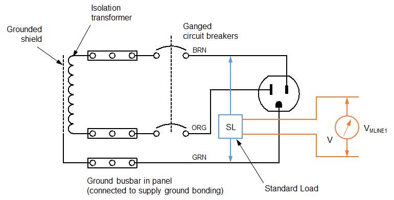
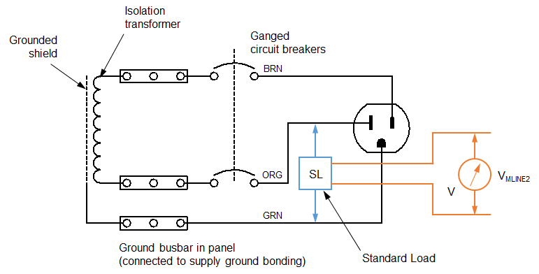
The test requires that a standard load (a device consisting of components that take into account the frequency dependent electrical sensitivity of a patient) is connected between an energized conductor and a reference ground.
Ideally, no current will flow between the energized conductor and the reference ground through the standard load.

For a single-phase isolated system, two measurements must be made:
- A voltage measurement (output from the standard load) when connected between L1 and the reference ground (VMLINE2). See the diagram above.
- A voltage measurement (output from the standard load) when connected between L2 and the reference ground (VMLINE1). See the diagram below.

L2 Impedance to Ground (Single-Phase Isolated System)
Test Procedure
Prior to making the required measurements, ensure that the system is functioning properly (receptacles, permanently connected equipment) and that the system is indeed isolated. Make sure all permanently connected equipment is switched off and that all cord connected equipment is disconnected (including line isolation monitors).
- Connect one end of the standard load between the energized conductor L1 and the reference ground (refer to instructions provided with the standard load being used in the test). Connect the other end to a voltmeter with an input impedance of at least 150 kΩ and record the voltage as VMLINE2.
- Connect one end of the standard load between the energized conductor L2 and the reference ground (refer to instructions provided with the standard load being used in the test). Connect the other end to a voltmeter with an input impedance of at least 150 kΩ and record the voltage as VMLINE1.
Test Results
When the test is complete, you will end up with two measurements at the output of the standard load:
- The measured voltage (input from L1 to ground), VMLINE2
- The measured voltage (input from L2 to ground), VMLINE1
There is a 1 kΩ resistor internal to the standard load where the connection between the energized conductor and ground is made. The current through this resistor produces a voltage measured by the meter. The measured current (in amperes) is the measured voltage divided by 1 kΩ. To convert the current from amperes (A) to microamperes (μA), multiply by 106 μA/A.
To simplify the calculation, the measured value (in volts) is multiplied by 1000 (which is 106 μA/A divided by 1 kΩ) to give the leakage current in microamperes (μA). Refer to Figure 3 within the CSA Z32 standard.
The leakage current (in μA) for each measurement may be calculated:
ILINE1 = VMLINE1 × 1000
ILINE2 = VMLINE2 × 1000
The value IMAX is the greater of the two calculated currents:
IMAX = max{ILINE1, ILINE2}
To pass this test, the following condition must be met:
IMAX ≤ 2E
where E is the nominal voltage between the energized conductors
Example
Suppose you perform the test on a 120 V nominal, single-phase isolated system using the standard load and recorded the following measurements:
VMLINE1 = 0.191 V
VMLINE2 = 0.186 V
ILINE1 = VMLINE1 × 1000 = 0.191 V × 1000 = 191 μA
ILINE2 = VMLINE1 × 1000 = 0.186 V × 1000 = 186 μA
IMAX = ILINE1 = 191 μA (it is the greater of the two values)
Since the nominal voltage between the energized conductors is 120 V:
2E = 2 × 120 = 240
Finally, as IMAX is not greater than 240 μA, the system has passed the impedance to ground test.
What to watch out for…
- Refer to CSA Z32 to ensure the isolated system is wired and functioning properly before performing this test.
- Ensure an appropriate standard load is used to perform this test. Injury can result if this test is performed on an improperly isolated system. The SL100A Standard Load is appropriately designed for this test.
How often should this test be performed?
This test is performed annually for systems without line isolation monitors and for multiple systems with line isolation monitors.
What test equipment do I need?
The SL100A Standard Load can be used along with a voltmeter to perform this test.
